Introduction
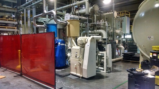
Northrop Grumman/AOA Xinetics is moving some vibration-generating equipment from its current location into relatively close proximity to a metrology room where various sensitive measurements are conducted. Specifically, current plans call for the vacuum pump equipment to be relocated within a few feet of the metrology room. The metrology room is situated on top of a floating floor assembly, but the details of the floating floor are unknown at this time. Both the vacuum pump and metrology room are at-grade on concrete slabs. This is helpful for the present analysis because it removes a potential variable of differing structural dynamics of one of the facilities being located (for example) on the second floor of the building.
Vacuum Pump Vibration Measurements
A seismic accelerometer was positioned on the floor 5’ from the vacuum pump spring mount, and vibration acceleration was measured in 1/3 octave frequency bands. Next, the same measurement was performed at 10’ from the vacuum pump in order to determine the vibration level drop-off rate as a function of distance. The acceleration data was then integrated to velocity (dB re: 1 µinch/second, also known as VdB). Figure 1 shows the results of this analysis.
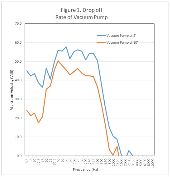
At the 5’ measurement location, the peak of 57.7 VdB occurred at 63 Hz. Human perception of vibration is around 65 VdB so this level is slightly below human perception. The data in Figure 1 can be used to calculate the vacuum pump vibration level at any distance.
Metrology Room and Adjacent Room Vibration Measurements
Next, vibration levels were measured both on the metrology room floor and the floor adjacent to the metrology room. Figure 2 shows the results of these measurements.
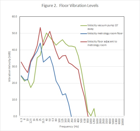
Vibration levels in the metrology room are at least 10 dB lower than the vibration levels in the floor adjacent to the metrology room. This difference is assumed to be caused by the floating floor system. Also characteristic of a floating floor is the lack of reduction below 20 Hz. Most floating floor systems have a low frequency limit of performance which is governed by the mass of the floating floor and the spring rate of the resilient elements. A caveat to these observations is that the source(s) of vibration are unknown in these two sets of data, so this 10+ dB reduction cannot be explicitly determined by this data.
The 10’ measurement data for the vacuum pump is also shown in Figure 2 for comparison with the metrology room data. While the 10’ data is higher than the metrology room data, it is roughly comparable to the data of the floor adjacent to the metrology room. This would suggest that a starting point would be locating the vacuum pump at least 10’ from the metrology room, thereby approximately maintaining the existing vibration level of the adjacent floor- which does not currently cause problems in the metrology room.
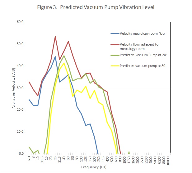
It is important to note that the frequency dependence of these data sets do not line up with each other- as expected. Consequently, a more conservative approach would be to reduce vacuum pump vibration levels at all frequencies to below the data for the adjacent floor. For example, Figure 3 shows the effects of locating the vacuum pump 20’ or 30’ from the metrology room. The 20’ data would be at or below the adjacent floor vibration data. The 30’ data would be well below the adjacent floor data and somewhat comparable to the metrology room data itself. In other words, positioning the vacuum pump at least 20’ to 30’ from the metrology room would cause vacuum pump-induced vibration levels to be conservatively lower than existing vibration levels in the room adjacent to the metrology room. It is assumed that the floating floor would then further reduce vacuum pump vibration levels to be at or below vibration levels in the metrology room.
Vibration Criteria for Sensitive Facilities
Figure 4 shows metrology room and adjacent room vibration levels compared to published vibration criteria for sensitive facilities. Vibration criteria curves A- E are described as follows:
• VCA --Adequate for medium- to high-power optical microscopes (400X), microbalances, optical balances, and similar specialized equipment.
• VCB --Adequate for high-power optical microscopes (1000X), inspection and lithography equipment to 3-micron line widths.
• VCC--Appropriate for most lithography and inspection equipment to 1-micron detail size.
• VCD --Suitable in most instances for the most demanding equipment, including electron microscopes operating to the limits of their capability.
• VCE --The most demanding criterion for extremely vibration-sensitive equipment.
The data in Figure 4 shows that the metrology room floor is currently at the most demanding criterion (VCE) for extremely vibration-sensitive equipment. Even the floor adjacent to the metrology room is at VCC, which is suitable to 1-micron tolerance.
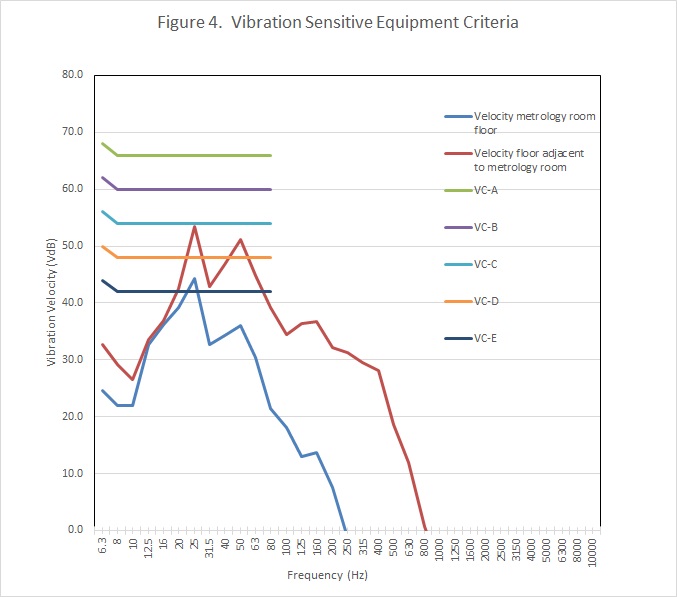
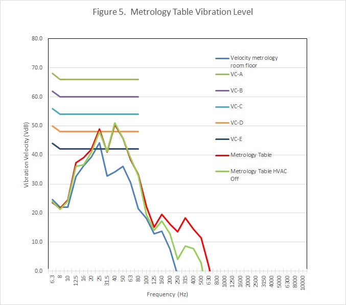
Figure 5 shows vibration velocity of the metrology table itself with HVAC on and off. This data shows that vibration levels on the table are substantially higher than the floor itself which indicates that either the table vibration isolators are not properly adjusted, or they are not properly specified for this vibration frequency range. However, even with this higher vibration level, table vibration levels are at the VCD criterion which is suitable for the most demanding equipment. As expected, the vibration excitation due to noise is relatively small at relatively high frequencies (315 Hz).
Noise Levels
Noise levels were measured in one third octave frequency bands in the metrology room and the room adjacent to the metrology room. Figure 6 shows these measured data, expressed in octave frequency bands for comparison with the “NC” Criteria. The “NC” Criteria are a published set of frequency based noise levels which are paired with descriptions of spaces suitable for such noise levels.
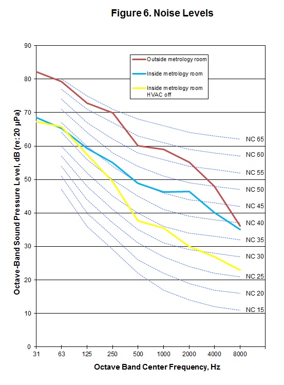
The room adjacent to the metrology room was at NC-60, which corresponds with “workspaces in which continuous speech communication and telephone are not required.” This is the highest NC level.
With HVAC off, the metrology room was at NC 40 which corresponds to “library.” With HVAC on, the metrology room was at NC 45 which corresponds to “laboratories.”
Summary and Recommendations
In summary, based on the measured data and analysis, relocating the vacuum pump 20’ to 30’ from the metrology room would keep vacuum pump vibration levels at or below existing vibration levels in the room adjacent to the metrology room. Assuming the previously discussed floating floor performance, metrology room vibration levels should be unchanged from current conditions.
I recommend that vibration measurements be conducted again after the equipment is relocated in order to verify the vibration levels discussed in this report. I also recommend that the vibration isolaters of the metrology room table be evaluated in terms of proper adjustment and/or specifications. In addition, it may be helpful to conduct vibration tests on the metrology measurements themselves (e.g., to failure) in order to establish more definitive vibration criteria for this facility. For example, it may be that the metrology measurements are more sensitive to other factors besides vibration. This information would be useful for other future potential relocations of equipment.